A Check valve is used to stop reversal of flow in a piping system.
Check valves are available in the following designs :
- Swing Check Valves
- Tilting Disk Check Valves
- Lift Check Valves
- Disk Check
- Piston Check
- Ball Check
- Duo-Check Valves
Swing Check Valves are available in straight body design and y-pattern design.The disk is suspended from the body by means of a hinge pin and seals against the seat which is integral with the body. These valves are typically used in sizes 2 inches and over. Swing check valves can be installed in both horizontal and vertical position. They are not suitable for pulsating flow.
Closure response of swing check valve is slower compared to lift check valve due to longer disc travel and inertia of disk.
Typical materials of construction for each part
| Sr. | Description | Material |
| 01 | Body | ASTM A216 Gr. WCB |
| 02 | Body Seat Ring | ASTM A105 +HF* |
| 03 | Disc | ASTM A216 Gr. WCB + 13% Cr. Steel |
| 04 | Hinge | ASTM A216 Gr. WCB |
| 05 | Disc Washer | 13% Cr. Steel |
| 06 | Disc Nut | SS 304 |
| 07 | Disc Nut Pin | 13% Cr. Steel |
| 08 | Hinge Pin | 13% Cr. Steel |
| 09 | Gasket | ASTM A308 |
| 10 | Cover | ASTM A216 Gr. WCB |
| 11 | Stud | ASTM A193 Gr. B7 |
| 12 | Stud Nut | ASTM A194 Gr. 2H |
| 13 | Hinge Pin Cover | ASTM A105 |
| 14 | Hing Pin Cover Bolt | ASTM A193 Gr. B7 |
| 15 | Name Plate | SS 304 |
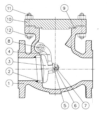
Flanged Swing Check Valve
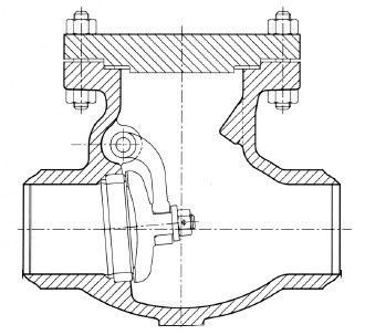
Butt Welding Swing Check Valve
Regular swing check valve is not suitable if flow reversal is frequent as it can cause pounding and wear of disc. A composition disc is used for gritty liquids to reduce damage to the seat. An optional lever and outside weight may be offered either to assist closing or to counterbalance the disc in part, and allow opening by low-pressure fluid.
Applicable Codes and Standards
- BS1868 :
- ASME B16.34 : Pressure Temperature Ratings.
- ASME B16.10 : Face to face and end to end dimensions of valves.
- ASME B16.5 : End Flange Dimensions.
- ASME B16.47 : Flange dimensions for flanges larger than 24″ Series A and B.
- ASME B16.25 : Butt weld end dimensions.
- BS 6755 Part I : Valve inspection and testing.
- API 598 : Valve Inspection and Testing.
Body and Bonnet Materials Based on Temperature and Fluid
| Material Classification | ASTM Specification | Working Temperature |
| Carbon Teel | ASTM A216 Gr. WCB | -29 deg C to 427 deg C (-20 deg F to 800 deg F) |
| 1-1/4 Cr – 1/2 mo | ASTM A217 Gr. WC6 | -29 deg C to 593 deg C (-20 deg F to 1100 deg F) |
| 2-1/4 Cr – 1 mo | ASTM A217 Gr. WC9 | -29 deg C to 593 deg C (-20 deg F to 1100 deg F) |
| 5 Cr – 1/2 mo | ASTM A217 Gr. C5 | -29 deg C to 649 deg C (-20 deg F to 1200 deg F) |
| 9 Cr – 1 mo | ASTM A217 Gr. C12 | -29 deg C to 649 deg C (-20 deg F to 1200 deg F) |
| 9 Cr – 1 mo – 1/4 V | ASTM A217 Gr. C12A | -29 deg C to 649 deg C (-20 deg F to 1200 deg F) |
| Low-temperature Steel | ASTM A352 Gr. LCB/LCC | -46 deg C to 343 deg C (-50 deg F to 650 deg F) |
| Austenitic Stainless Steel / 18-8 (Type-304) | ASTM A351 Gr. CF8 | -196 deg C to 649 deg C (-320 deg F to 1200 deg F) |
| Austenitic Stainless Steel / 16Cr – 12ni – 2 mo (Type 316) | ASTM A351 Gr. CF8M | -196 deg C to 649 deg C (-320 deg F to 1200 deg F) |
Body Gasket Materials / Type based on Rating
| Rating | Typical | Optional |
| 150 | Spirally-wound SS 304 with Graphite filler | Spirally Wond SS 316 with Graphite Filler / Spirally wound SS 304/SS 316 with PTFE filler |
| 300 | Spirally-wound SS 304 with Graphite filler | Spirally Wond SS 316 with Graphite Filler / Spirally wound SS 304/SS 316 with PTFE filler |
| 600 | Spirally-wound SS 304 with Graphite filler | Octagonal Ring Type (RTJ) metal gasket in soft iron / Octagonal Ring Type (RTJ) metal gasket in SS 304 / SS 316 |
| 900 | Octagonal Ring Type (RTJ) metal gasket in soft iron | Octagonal Ring Type (RTJ) metal gasket in SS 304 / SS 316 |
| 1500 | Octagonal Ring Type (RTJ) metal gasket in soft iron | Octagonal Ring Type (RTJ) metal gasket in SS 304 / SS 316 |
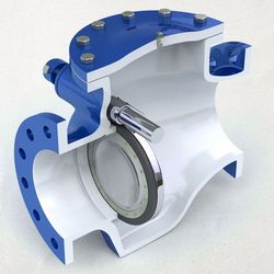
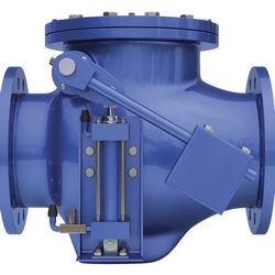
Tilting Disk Check Valves
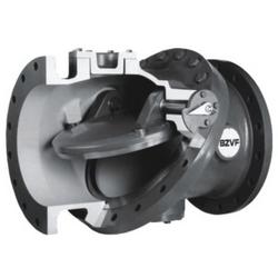
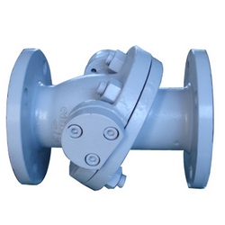
Tilting Disk Check Valves fit between two flanges and provide a compact installation for large diameter applications. These valves can be installed in horizontal and vertical lines. They provide a faster closing response and are particularly suited for pulsating flows with compressible fluids.
Lift Check Valves
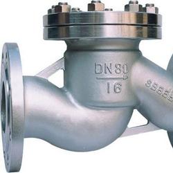
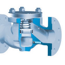
Lift Check Valves are available in disk,piston and ball type design. Some designs use spring to return the closure member to the seating position. These valves are used in smaller sizes, generally below 2 inches. These type of valves have a higher resistance to flow. Y-type designs are available with lower pressure drops across the valve. The spring loaded design can be used in both horizontal and vertical position. Without the spring loading this design must not be used in vertical position. Closure response of check valves is relatively fast due to shorter lift and low inertia of closing member.
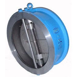
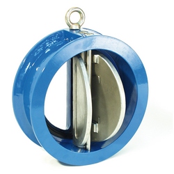
Duo-Check Valves
Duo Check Valves have two disks and rely on internal spring loading for closure.Check valves are extremely sensitive to upstream piping configuration such as bends, valves. It is recommended that check valves be placed atleast 3 pipe diameters away from such obstruction.
Industry Codes and Standards
- API 6D - Specification for Pipeline valves
- BS 5152 - Cast Iron globe and globe stop and check valves (withdrawn)
- BS 5352 - Cast and forged steel gate, globe,check and plug valves, screwed and socket welding ends (<= 50mm)
- BS 1868 - Specification for steel check valves (flanged and butt-welding ends)
- MSS SP 61 - Pressure testing of steel valves
- MSS SP 25 - Standard marking system for valves, fittings, flanges & unions
- MSS SP 45 - Bypass and drain connections


